By Ben Kuster
Computational-fluid-dynamics (CFD) software is an invaluable thermal-analysis weapon for the electronics design arsenal. At VT Miltope Corp. in Boulder, Colo., it saves weeks of development time and thousands of development dollars-even on small projects.
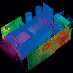
A CFD simulation presents a window into an electronics design, enabling an engineer to pinpoint hot spots and follow air across a board or through a chassis. The analysis predicts temperatures at every point, including points that are physically impossible to measure.
An overlay of temperature and airflow graphics can enable the engineer to detect interactions between the two. In addition, a variety of other parameters-such as the heat flux vector and its components, pressure, turbulence, and intensity-can be calculated and displayed.
When the engineer finds a thermal problem he can quickly modify the design, reposition components, change fans, replace heat sinks, thermal pads, or add vent, and then recalculate the results. No prototyping is necessary.
Sometimes, an engineer believes he intuitively “knows” how cooling air might flow or where the hot spots will crop up, only to encounter unexpected eddy currents, fans, and vents that are poorly located, or heat sinks that are undersize. CFD analyses eliminate this guesswork and delivers predictions accurate to within 10 percent or better.
Building the model
To construct a CFD model, the designer first creates a 3-D solid model of his design, and then specifies the solution domain and ambient conditions. Next, he specifies component properties such as thermal conductivity, power dissipation, or perhaps a fan curve. These are usually available in the CFD software library.
Once the model is built, the software divides the domain into a contiguous set of grid cells (finite volumes) and then calculates its way from cell to cell. Typically, fine-grid cells produce more-accurate solutions, but take longer to calculate than coarse-grid cells.
Coolit analysis of a digital mass-storage system for the Air Force’s C-130 predicts component temperatures will remain below maximum temperature specifications even under worst-case power dissipation.
For fast results, the engineer may choose coarse grids when comparing early design scenarios, and then switch to fine grids for the final design stage for better accuracy. Fine grids also should be used where a solution is expected to change rapidly, such as near inlets and outlets and around certain components.
Avionics mass storage
For a major Boeing avionics upgrade to the Air Force’s C-130 aircraft, VT Miltope developed a digital mass-storage system to collect high-speed digital map and ground terrain data. The system contains a chassis-mounted processor, high-speed interface, and sealed removable 146-gigabyte hard-disk drive (HDD).
Design requirements specified 10.1 pounds per square inch of air pressure and steady-state operation at 55 degrees Celsius, with 30 minutes of operation at temperatures as hot as 71°C. For operator safety, equipment surfaces could not exceed 11°C above ambient air temperature.
The HDD, which dissipates 16 watts maximum, is cooled by a 102-cubic-foot-per-minute muffin fan that draws air from the front of the chassis. Initially, the design goal was to use a standard drive cartridge. Using Coolit CFD software from Daat Research Corp. in Hanover, N.H., engineering modeled the design and found that the standard drive cartridge would overheat.
To boost convective heat transfer, designers added cooling fins, yet while the fins improved performance, they did not solve the problem. When the software’s flow visualization capabilities (stream ribbons) were activated, engineering discovered that much of the air was bypassing the fins. To increase cooling efficiency, they added an air duct to funnel the air and boost its velocity through the fins.
The final step was to analyze the remaining components. The power supplies, processor module, server electronics, Fibre Channel, and Gigabit Ethernet chips are mounted via a thermal pad to a custom aluminum heat-spreader plate that sinks heat to the chassis’ aluminum right sidewall.
Because of difficulties in identifying actual power dissipation for the chips, the thermal analysis was performed assuming maximum power dissipation, a worst-case scenario. Even under these conditions, Coolit predicted component temperatures would be below the maximum temperature specifications. Once completed, the design was subjected to final Verification Testing that validated the predictions.
Mortar fire-control computer
A sealed, ruggedized, mortar fire-control computer system for the U.S. Army drew 26 watts steady-state, spiking to 67 watts when two removable batteries were charging. Operating ambient temperatures ranged from -25 to 125 degrees Fahrenheit, while the unit was simultaneously exposed to ballistic shocks as strong as 125G.
Severe shock and vibration, coupled with extremely high reliability requirements, meant fans were not a cooling option; they couldn’t withstand the environment. The best alternative appeared to be direct conduction cooling of the processor module components through the chassis. Initially only the processor and video chips were targeted for conduction cooling, but Coolit simulations revealed that more chips than originally thought would require sinking in a 125°F ambient to remain below their maximum temperature specifications.
Using the CFD software, engineering designed a custom aluminum heat sink by examining the conduction sinking of different chips. They compared thermal pads of different thicknesses and conductivities, and studied the impact of various ambient temperatures. Performing these studies without CFD analysis would have required an additional three to four weeks of thermal prototyping and testing. When the preproduction hardware was built and tested, the thermal model predictions proved to be accurate to within 5 percent.
As military and aerospace electronic packages shrink in size, designs become increasingly sensitive to slight changes in component position, vent, and fan locations, and heat-sink design. CFD analysis is the only method that will quickly and effectively analyze these designs and deliver an optimum thermal solution.
In addition to delivering accurate predictions, typically within 5 to 10 percent, CFD analysis slashes development times and project costs, making it an indispensable tool for a competitive engineering organization.
Ben Kuster is a senior mechanical engineer at Miltope Corp. in Boulder, Colo. He has 15 years experience in mechanical engineering design and thermal management.

