Measuring radar PRI stagger during walkoff
By Mike Hertz of Teledyne LeCroy and Steve Shafer of DRS Technologies
Accurate time domain measurements, such as pulse repetition interval (PRI) stagger during walkoff have not been possible using traditional frequency domain equipment. With the advent of ultra-high-bandwidth, real-time oscilloscopes, and timing parameter tracking, electronic countermeasures (ECM) flightline tests such as gated PRI, PRI stagger variation, and parametric timing measurements of a demodulated pulse are now possible on an F-16 Aircraft configuration with coupler and measurement system.
Many techniques can be employed by aircraft to avoid radar detection. A common radar deception method used by military aircraft is the re-transmission of incoming radar pulses while applying a gradual Doppler shift. This Doppler shift mimics the effect of velocity occurring at a different speed and/or direction than actual.
Pulse repetition interval (PRI) is the distance in time between subsequent radar pulses. By staggering the PRI in uniform time increments, electronic countermeasures (ECM) techniques allow for aircraft to potentially avoid being tracked by search radar by returning a radar signature indicating false aircraft speed and direction. The ground-based radar then gradually walks off from the actual target while continuing to track false target range information, and the evading aircraft disappears from radar due to velocity track breaking.
The ultra-high-frequency content of X-, K-, V-, and W-band radar signals have traditionally required spectrum analyzers and frequency domain equipment to be used due to the historically higher bandwidths of spectrum analyzers and lower bandwidths of real time oscilloscopes. A spectrum analyzer is able to determine frequency content of a signal, but the measurement challenge has been that these frequency domain instruments cannot characterize timing information accurately. However, with the advent of ultra-high-bandwidth oscilloscopes in the recent few years (analog oscilloscope bandwidths have now crossed the 100 GHz real-time threshold), the full spectrum of radar signals up to W-band radar can be acquired. The use of time-domain equipment to acquire radar signals now allows accurate ECM flightline tests including gated PRI, PRI stagger variation, pulse duty cycle, and other parametric measurements of a demodulated pulse and parameter tracking, each of which are described below.
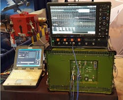
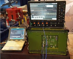
Figure 1 depicts an example hardware test configuration, consisting of an F-16 coupler, a real-time oscilloscope, and a radio-frequency stimulation and measurement unit. The RFSM unit is programmed to generate PRI stagger, and is connected to the oscilloscope via a 2.92mm cable.
Figure 1: Hardware configuration for electronic countermeasures flightline test
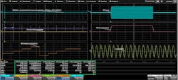
The blue waveform in the topmost grid of Figure 2 shows an acquired series of radar pulses, in which long idle gaps occur between bursts. The timebase setting corresponds to a 2 millisecond time capture window of 160 million contiguous sample points (Mpts) captured at 80 gigasamples per second (GS/s). The orange waveform in the second grid utilizes a demodulation math operator to produce an envelope of each radar pulse. The third grid shows a zoom trace (blue) with a demodulated waveform overlay of a single pulse, and the fourth grid (green trace) shows a zoom-on-zoom display of the carrier at 200 picoseconds per division.
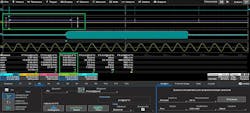
The parametric period measurement, parameter 3 (circled in green), reports the period of function F1. The function F1 has demodulated the radar pulse and displays an envelope of each burst. Parametric timing measurements are applied directly to the demodulation math operator, and the period parameter directly calculates the PRI of the series of radar pulses during walkoff. With measurement gates bracketing the first two pulses, the PRI is found to be a 510.0024 us (microseconds), forming a gated PRI measurement.
Figure 2: Gated PRI measurement of 510.0024 us PRI stagger during walkoff
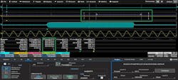
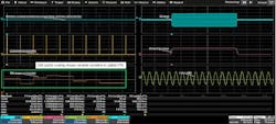
Moving the measurement gates to each consecutive set of pulses follows the change in PRI, and in Figure 3, bracketing the third series of pulses reveals a PRI of 520.0013 us stagger during walkoff.
Figure 3: Gated PRI measurement of 520.0013 us PRI stagger during walkoff
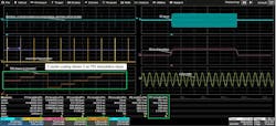
Larger real-time acquisitions provide even greater insight into system behavior. By acquiring 400,000,000 contiguous sample points (with each point sampled every 12.5 picoseconds (ps) consecutively during a 5-millisecond time capture window, a larger picture emerges. The frequency and period are calculated directly on the demodulated waveform as the pulse repetition frequency and pulse repetition interval shown in parameters P2 and P3 in Figure 4. By applying a Track math operator (the orange Function F5) to parameter P3, the PRI stagger is accurately graphed as a function of time and appears with a distinct stair-step shape. Further measurement and math operators can be applied onto the Track for detailed analysis of the PRI stagger, as it now exists as a real waveform trace.
In addition to the PRF and PRI calculated in parameters 2 and 3, parameter 1 reports the carrier frequency of the blue zoomed region Z3. Parameters 4 and 5 measure the rise times of the pulse envelope and the carrier respectively, and parameter 6 measures the width of the demodulated RF pulse envelope.
Figure 4: 400 Mpts acquisition (5-millisecond capture window) with PRI plot, and RF burst parameters including PRI, PRF, radar carrier rise time, and rise time and width of the demodulated pulse envelope.
When PRI stagger is not employed as a ECM technique, the minute PRI variation of consecutive radar pulses is random. With PRI stagger disabled, the track of PRI shown in Function F5 of Figure 5 confirms this random variation. Note that the Y-axis autoscaling of Function F5 is 500 ps/div during random variation in Figure 5, compared with a 5 us/div autoscaling of F5 in Figure 4 when PRI stagger was enabled. Note that if the Y-axis scaling of random PRI variation had been set to 5 us/div to match Figure 4, then the PRI track in Figure 5 would appear as a flat line (indicating no PRI stagger was present).
Figure 5: PRI plot shows random ppm variation in stable PRI: 500.0014 us to 500.0026 us with 500 ps/div Y-axis track auto-scaling
PRI is re-enabled in Figure 6, and an additional measurement parameter is added to the measurement table. Parameter P7 now calculates the duty cycle of the demodulated radar burst envelope and reveals an extremely low characteristic radar duty cycle of 0.193214%. This type of measurement would not be possible without first demodulating the radar pulse. Otherwise, the duty cycle measurement parameter would be applied to the carrier oscillations instead of the demodulated pulse.
Figure 6: The PRI plot shows PRI stagger variation from 500 us to 520 us. A duty cycle measurement parameter of the demodulated pulse measures a 0.193214% duty cycle.
In the recent past, the use of frequency domain equipment has prevented the ability to accurately characterize timing information such as PRI stagger during walkoff. With recent developments in ultra-high bandwidth real time oscilloscopes, the defining timing characteristics of a radar system such as pulse duty cycle, PRF, and PRI stagger during walkoff can be accurately characterized within the fields of radar and electronic warfare now using parametric tools in the time domain.
About the authors
Mike Hertz has been a Field Applications Engineer with Teledyne LeCroy in Michigan for 16 years. Before joining Teledyne LeCroy, he worked in Applications and Marketing with both Agilent Technologies and Hewlett-Packard in Colorado. He holds a BSEE from Iowa State University and an MSEE from the University of Arizona. Hertz is an Eta Kappa Nu electrical engineering honorary recipient, has published over 45 articles in the field of test and measurement, and has been awarded 6 U.S. patents in oscilloscope measurement design.
Steve Shafer has over 40 years of experience in Electronic Warfare (EW) intelligence, operations, and maintenance, serving both in the United States Air Force and in the EW industry. He directly supported daily operations for B-52, U-2, and A-10 aircraft for 14 years, and spent 4 years at HQ Strategic Air Command in the EW Systems Engineering group working on EW Area Reprogramming applications. Steve has spent the last 14 years as Program Manager and Chief Engineer for DRS Technologies, developing flight-line end-to-end test capabilities for US and foreign air forces.
