Designing commercial aircraft TRAS: How to specify the right flexible shafts
By Steve Grimes, Director, Sales & Marketing, S.S. White Technologies
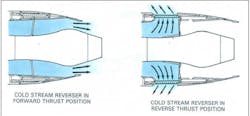
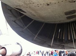
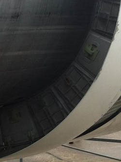
ST. PETERSBURG, Fla., - Thrust Reverser Actuation Systems (TRAS) redirect aircraft engine thrust immediately after landing to brake. On commercial jets, these systems provide critical safety and maneuverability to pilots. Failure to deploy correctly during a landing could cause unsafe turning as an engine on one wing brakes while the other continues forward thrust.
Even more dangerously, a poorly designed TRAS can rattle out of place during flight, effectively disabling an engine thousands of feet from the ground. Therefore, as is the case with most aerospace engineering, excellence in TRAS design is a necessity. Understanding the characteristics of a key functional component—the flexible shaft—is vital to a configuring a successful TRAS. As an engineering team begins the initial design phase for a TRAS, it should consider what makes flexible shaft technology appropriate for aircraft engines, and what specifications best serve the application.
Flexible Shafts in Basic TRAS Designs
Commercial aircraft fly on Larger Turbo Fan gas turbine engines, and Thrust Reverser Actuator Systems operate by >Figure A. For commercial airplane engines, S.S. White flexible shafts move actuators that change the direction of cold bypass air.redirecting the cold “bypass” air,The actuators must move together in a synchronized fashion; a non-synchronized deployment can lead to the system jamming. This results in asymmetrical braking, affecting the pilot’s ability to control the aircraft. Both principle system
In a hydraulic TRAS system, these flexible shafts are passive—their sole function is to ensure the actuators deploy and stow synchronously to prevent panels from jamming the system. In this design, the flexible shafts are contained within the hydraulic tubes that deploy the system, and so are lubricated by the hydraulic fluid. These systems generally support lower torsional loads.
Key Flexible Shaft Characteristics for TRAS Applications
Beyond the basic considerations of load, deflection endurance, and fatigue characteristics, a variety of additional flexible shaft characteristics define the components’ utility in TRASs. These can be organized into three categories: Performance, Assembly / Material, and Installation.
Correctly positioning actuators is a necessary function of flexible shafts in these systems. This positioning depends mechanically on the angular position between the ends of each shaft. Therefore, angular deflection / torsional stiffness, which is proportional to applied torque and flexible shaft length, asserts itself as a key performance characteristic.
Other important performance characteristics deal with stresses on the system. For example, TRASs must accommodate shock from a variety of sources, including “back driving” or static torque loads caused by system architecture or aerodynamic effect and “torque spikes” at the end of the stroke when the system hits its end stops when a system’s inertia may be absorbed by the torsional elasticity of its flexible shafts. Depending on TRAS configuration, flexible shafts’ ability to absorb shock loads can prove highly advantageous.
Likewise, change in angular deflection over time should be controlled, as wear over a number of cycles can be expected toTo best integrate flexible shafts into a cohesive and durable system, engineers must consider the long term and design with several material and assembly characteristics in mind.
Firstly, materials should be selected with the following in mind: electrical bonding path, in case of lightning strike; tribological (bearing) couples, with suitable materials for bearings designed to contact each other; galvanic couples, with materials that guard against long term corrosion; etc. Different materials offer a number of distinct benefits for certain applications and can affect how flexible shaft constructions operate within a TRAS. More fundamentally, any system using flexible shafts must competently fit those shafts into an overall assembly.
For this reason, engineers must give careful consideration to the radial clearance between the shaft and the casing. This clearance will limit the amplitude of the helix, and also the wavelength, of the flexible shafts. This is often influenced by the support clamp spacing, and by the bending stiffness of the casing due to the tendency of a flexible shaft to helix during operation.
Then, when determining the length of the flexible shafts in a design, engineers must factor in the likely routing of the shaft compared to the routing of its casing. The centerline path of the installed shaft may be longer than the housing, meaning the shaft should be longer in turn. In some circumstances, a devise may be needed to retain the shaft in its casing to ensure its correct positioning.
Of course, the best designed system will fail if incorrectly or insecurely installed. If loose flanges are specified, for example, the engineering team may decide to develop a feature to retain them and prevent their falling from one end to another. Installation can also be foolproofed, by designing assemblies of differing lengths. When this is impossible, as in the many cases for which both shafts with dominant characteristic in clockwise and counterclockwise directions are required to be of identical length, creative engineers may select differing fitting types—square and hexagon cross section fittings, or fittings with alternate numbers of spline teeth—to prevent a detrimental incorrect installation. Another option to design for quality installation involves a trade-off. Assemblies can be “locked in” to aid installers, and prevent inner flexible shafts from separating from their casing, but this can inhibit maintenance and examination.
Flexible Shaft Experts Provide TRAS Engineering Insight
Whether designing a hydraulic or motor driven system, TRAS engineering teams must consider an array of flexible shaft