Systems designers who are used to boosting electronic system performance by adding ever-more transistors may shortly have to rethink their design approaches, as increasing amounts of heat–and the need to remove it–may be making the brute-force approach to system capability obsolete.
By J.R. Wilson
From ultra-high-power, directed-energy weapons to three-dimensional chip-stacking for added compactness, from network-centric battle theaters to all-electric fly-by-light commercial jetliners, the requirement for advanced thermal management at the chip, board, and box level continues to grow in importance and complexity with each new generation component emerging from military and commercial research-and-development labs.
“The industry is seeing an increasing need to leapfrog the next-generation solutions,” says Steve Krein, vice president of spacecraft systems & services operations at ATK Space Systems in Beltsville, Md. “Leaving thermal as an afterthought is a backwards approach. If we can engage inside the box and help drive the design of the chip, board, and box, it makes the overall architecture at the vehicle level that much more flexible.”
In a world driven by SWaP (size, weight, and power) on one side and smaller-faster-denser-hotter integrated circuits, multi-function sensor fusion boards and increasingly high-tech line-replaceable units (LRUs) on the other, dealing with temperature extremes means not only addressing the issue at the point of origin, but also moving excess heat through the package and off the platform.
“Many of the techniques being used at the component level–using better materials or heat spreading–are addressing the issue locally, but you still have to get the heat out of the box and off the vehicle. They still require chilled air to move that heat,” says Joe Baddeley, executive vice president for sales and marketing at SprayCool in Liberty Lake, Wash. “Liquid cooling in general and spray in particular address the whole problem–removing heat from the component and getting it out of the vehicle into the ambient.”
Gerald Janicki, senior director for thermal systems business development at Meggitt Defense Systems in Irvine, Calif., agrees that many ways exist to address individual thermal management concerns, yet the best overall solution is an original architecture that best employs several capabilities.
“Some of the more boutique solutions, such as spray cooling, have their place,” Janicki says. “But designing cards that are better able to conduct heat loads to the side walls or to a surface material tied to the sidewalls–then combining that with a passive or active air or liquid solution–can mean a lower cost all around for everybody. We look at all the technologies across the board and typically gang a few together to meet a system solution.”
Once the SWAP requirements are defined, engineers must consider the internal systems available in the vehicle, down to the most basic approach–brute-forced air.
“Two hundred watts of air cooling is difficult to do for a card. Liquid cooling, which a lot of people favor today, can only be taken so many degrees above ambient–say 600 watts; it becomes difficult to do unless you have a heat exchanger in the loop,” Janicki says. “If you don’t have enough power, you can actively cool the liquid through refrigeration if you have access power for thermoelectrics–but you typically have to put 3 kilowatts in to get 1 kilowatt out. So we have to be smart consumers of all these technologies.”
Thermal management research
Thermal management has become a high priority for the military, commercial manufacturers, and academia. Those include the Air Force Research Lab’s Power and Thermal Management Technology Development Program (PATH), the Naval Research Lab’s Thermal Management Discovery and Invention Program, the Defense Advanced Research Project Agency’s (DARPA’s) ultra-high-capacity hybrid thermal ground plane development project and dozens of corporate and academic research-and-development efforts.
“New materials are being developed on a continuing basis, but from my perspective we are still in the infancy of this technology,” says Dr. Carl Zweben, an independent consultant on thermal management and composite materials. “What these new materials do is give the design engineer or packaging engineer a greater range of options, but be aware of the possible need to do some development work to introduce new materials into your design and manufacturing process. There are just too many different requirements, including weight, cost, and degree of risk for a universal solution.”
Zweben, who was a division fellow and director of the General Electric Aerospace Group Composites Center of Excellence, says thermal stress and heat dissipation problems led to the development of traditional thermal management materials with a low coefficient of thermal expansion (CTE).
Although early efforts had problems balancing CTE, density, and thermal conductivity, “about five or 10 years ago, new materials with low CTEs and better thermal conductivities came along. These materials are being used to package various types of high-temperature semiconductors made from silicon, gallium arsenide, and silicon carbide.
New thermal management materials that have come to light over the past decade include composites, such as diamond particle-reinforced aluminum, silver, or copper; a ceramic matrix of silicon carbide reinforced with diamond particles; diamond particle-reinforced cobalt; and carbon-based materials like natural graphite and highly oriented pyrolytic graphite (HOPG).
“The cheapest and most efficient way to go, of course, is natural convection, followed by forced convection, which means you put on a fan, but that also means you are drawing power and adding weight,” Zweben adds. “Then you have heat pipes and pumped liquid cooling, but those are expensive–so there are advantages and disadvantages for all these techniques. No matter what approach you use, if there are large excursions in the ambient temperature, you will have thermal stresses.”
Systems designers must address three basic issues in thermal management for military electronics applications: high enough thermal conductivity to dissipate heat, a low CTE to reduce thermal stresses and solder attachments, and low-density thermal interface materials (TIM).
Design tradeoffs
“If you use a copper heat spreader with silicon, copper has a high expansion so you are forced to use compliant TIMs–polymeric (adhesives) or solders, which provide the lowest thermal resistance,” Zweben says.” But you can’t use hard solders if you have a large difference in CTE.”
Electronics really began to drive the need for cooling systems on ground platforms, Janicki says. “When they began adding things to new tanks, we realized, even though there was some cooling available, it wasn’t sufficient as these 100-watt systems were added in,” he says. “The commander, who now uses a touchscreen command post, found the panel was hotter than 95 degrees and could not tell the difference between a human touch and anything else.”
Each environment has its own unique problems, from keeping the fine sand of Iraq from clogging systems drawing air from outside, to avoiding a spiked heat signature on a stealth aircraft, to the inability to correct any problems that may arise once a spacecraft has been launched. Weight also is an important consideration in aircraft, spacecraft, man-carried field equipment, etc., as well as for shipboard applications, where rough seas or explosions can create shock load stresses.
While weight and size are important in spacecraft design, operating in a weightless, thermally harsh, high-radiation environment with little or no repair capability brings a whole new set of thermal management problems. In designing future satellites and man-rated platforms, engineers must consider higher flux levels and higher power electronics–elements that, to a somewhat lesser degree, also are increasingly driving vehicle-level challenges and accommodations in aviation.
Space-based requirements also are driven by a continued need to incorporate commercial off-the-shelf (COTS) components, not only to ease scheduling pressures but also to reduce costs. For payloads intended to operate for years without maintenance, higher thermal flux levels and solutions are making it increasingly important for thermal management engineers to be part of the design process early on, enabling them to deal with that aspect of the architecture at the lowest possible component level.
Cooling in space
“In solutions for space, we try to use a generic set of building blocks with thermal control tools to the extent possible, but implementing those for unique point solutions sometimes requires customization,” ATK’s Krein explains. “There also is a bifurcation of the man-rated and unmanned space environments. With an internal habitability requirement, there is the luxury of some low-level convective cooling. That element does not exist in an unmanned spacecraft.
“The need to use conduction and high order transport devices, either two-phase or next-generation composites, for radiated projection into space is more challenging. The extremes of the space environment–eclipse durations, solar impacts, etc.–make issues like freeze tolerance a much more applicable concern than for a ground-based system.”
The evolution and development of next-generation thermal control applications also is far less flexible and forgiving in space than for ground or aviation systems, making maturation of such solutions a first order consideration in any system development. “The lack of a second chance if there is a failure really drives the inherent reliability of good thermal control to the forefront of any application,” Krein says.
While densities, power requirements, and heat generation have been on a steady uptick in all electronics–especially in the last two decades–the numbers for future generations of equipment clearly demonstrate the problems facing system designers.
“For the next five years, I think we have the basic components ready and available,” says Dr. Kim Wrenn, ATK’s manager for advanced thermal technology; that does not, however, mean the engineers can relax. “We are approaching our limits on passive systems in space, using heat pipes without any mechanical pumps.”
At a recent spacecraft thermal control workshop, government agencies presented their thermal management roadmaps for the next five years, but Wrenn believes those maps already are obsolete. “The government lab roadmap had pumped single-phase listed as the next solution and pumped two-phase as the solution after next. I think they will be able to go directly to two-phase.”
Leapfrog technology
Going directly to a two-phase solution “will be an enabling technology for future space vehicles,” Krein adds. The evolution from standard one- and two-phase capillary devices to two-phase pumped devices would enable the next level of magnitude for heat absorption and transmission–and accomplishing that as quickly as possible is mandated by the extrapolation of historic requirements growth.
“We’re reaching a point in the market where some of the cutting-edge, higher-power vehicles are approaching 20 kilowatts. We see these approaching 40 kilowatts in the next three to four years, so there certainly is a point where we must ask if current techniques, using heat pipes and distributed vehicle management, will meet those needs. Or are mechanically pump-assisted solutions going to be required? Right now, our internal roadmapping says that is the way the industry is going,” Krein says. “On the space side, I also expect to see some of the experimental technologies being evolved into widespread use in the next three or four years–electrochromic devices for radiator IR transmission and the evolution from two-phase passive to pumped two-phase devices to increase by a significant level the acquisition and transport efficiency of these next-generation systems.”
Five years also can be seen as a hurdle when dealing with something that moves as quickly and dramatically as electronics.
“If you develop a new thermal system today, based on new technology, it won’t be ready for three to five years–and by then you’ve passed through the obsolescence cycle,” Janicki says. “So you have to project a little farther and have at least enough margin to accommodate 100 percent thermal load. The trend is precise cooling, using systems designed around missions and mission requirements rather than just a general cooling system. And one cooling system for the whole vehicle just isn’t the answer; you need multiple cooling systems–maybe one active and two passive.”
Within a system, he adds, three things drive any cooling requirement:
- What is the internal load, which may be abated by coatings on the vehicle;
- How are the electronics arranged within the system–there must be enough thermal inertia in the system to still operate mission critical functions even if cooling fluid stops flowing in a worst case scenario; and
- Parasitic loads, from boxes setting too close to each other, some with air cooling, some with liquid; it isn’t just the box itself, but where it is placed in proximity to other boxes–or even people–generating heat.
“My philosophy would be to work toward simpler, lower-temperature cards, so everything operates commercially at 50 C rather than 100 C,” Janicki says. “There may be some great savings, not only today but as you upgrade tomorrow, with lower-temperature COTS cards that require less external cooling. That really changes the paradigm for electronics. You don’t actually have to change the MILSPEC, you just have to change how much of that requirement reaches down to the card level.”
COTS cooling concerns
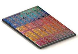
The COTS element of future solutions–typically triggered by COTS technologies raising the thermal management bar–was highlighted at the 2009 International Consumer Electronics Show in Las Vegas, where AMD president and CEO Dirk Meyer’s key-note speech included a warning that his company’s CPUs have hit a thermal-induced clock speed ceiling. Intel previously acknowledged the same problem, leading to the creation of multicore chips as a temporary solution. But Meyer emphasized the “temporary” nature of that effort. “Throwing more and more transistors at the performance problem in the form of increasing core counts, burgeoning cache sizes, and the like is producing diminishing returns,” he says.
Another attack on rising heat levels is being introduced by Nextreme Thermal Solutions in Durham, N.C., which has proposed removing heat from the front side of the die.
“Nextreme is removing the heat laterally through an interposer, so you can imagine some of the chips would be below an interposer and the interposer would be at a fixed temperature,” says Paul A. Magill, Nextreme’s vice president of marketing and business development. “You’d mount the rest of the chips on top, the least heat-generating chips, and could use a classical means such as fan and heat sink for heat removal.”
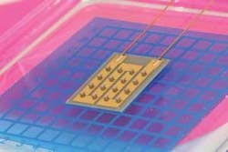
The approach involves the use of thermally active copper pillar bumps with embedded thin-film thermoelectrical material, a Nextreme development to rapidly cool one side relative to another by running a current through them. Magill says the method is a scalable and cost-efficient approach to thermal and power constraints in electronics. In a 3D chip stack, for example, several bumps placed in various layers, including a passive layer used strictly for cooling, could provide active-side, back-side, and lateral cooling.
“If you don’t want to take the heat out through all the other chips in the stack, it’s potentially going to be removed through the substrate. And copper-filled vias are the primary candidate for doing that,” Magill adds with regard to what he terms a more holistic approach to 3D thermal management substrates. “People are investigating other methods for 3D chip stack cooling–for example, microchannel cooling with liquids–but that introduces a mechanical aspect into the system, making it inherently less reliable than electrical devices because of the moving parts. We need to start thinking a little differently about 3D thermal management.”
Throughout the thermal management arena, a variety of materials and techniques are being employed, some as single-point solutions, others as tandem applications, which include customized absorptance and emittance coatings; thermal control paints; thin-film thermoelectrics; dielectric and conductive coatings; tapes; lacquers; phase change materials; thermal louvers and switches; composite panels, tubes, struts, and assemblies; replacing solid metallic heat spreaders with an advanced passively driven, internally liquid-cooled, silicon carbide-based thermal ground plane; carbon nanotube coatings; buffered loop thermosyphons; resin fused through the lead frame of a tantalum capacitor to conduct and dissipate heat; thermoplastic composites; pulse tube coolers; jet impingement; emersion cooling; monolithic carbonaceous materials and metal matrix, carbon/carbon, ceramic matrix, and polymer matrix composites.
Spray cooling
Methods such as spray cooling, a subset of liquid cooling that once was considered too exotic, are now edging into the mainstream.
“A few years ago, liquid cooling of any type was considered exotic, but most industry experts did see it as perhaps inevitable. Now there are several applications in the processing world–sensors, C4, power electronics, EW, etc.–where people are starting to not only view liquid cooling as necessary but as a viable option–and not so exotic,” Baddeley says.
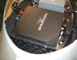
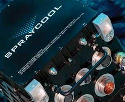
“Liquid flow through (LFT) with conduction-cooled solutions, liquid cooling loops with coldplates mounted to hot spots, and spray cooling are all variations of liquid cooling, but where the others essentially are conduction mounted coldplates, we directly spray fluid onto electronics,” Baddeley explains. “With immersion cooling, you are completely filling the enclosure with liquid, making it very heavy. In our enclosures, about 7 percent of the volume is liquid; the rest is vapor, so you don’t have the weight issues. Another key difference is spray takes advantage of the efficiency of two-phase evaporation, where many emersion systems are single-phase. And when components get hot enough, the emersion liquid starts boiling. So those are not as efficient as two-phase evaporation.”
In a spray-cooled system, as components get hotter, the spray evaporates more quickly, changing phase without boiling. “The faster it happens, actually, the better it cools, which is one of the beauties of spray cooling–you can tune the amount of fluid you want to evaporate depending on the power of the component. A processor will evaporate more fluid than a lower-power component, for example,” Baddeley adds.
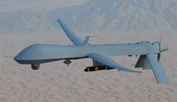
“Components are continuously sprayed, so we don’t have to know if the component is on a hot duty cycle,” continues Baddeley. “But we do measure the internal ambient temperature of the fluid to determine if it is hot or cold; if it is very cold, we will warm up the fluid. In a UAV application at high altitude, it could be -60 C. One difference with spray cooling is we are typically asked to field commercial-grade cards, which don’t operate very well below 0 C, so we warm up the fluid to that point, then apply power to the backplane. Think of it more as a temperature control system, like a home thermostat that sometimes uses the air conditioner, sometimes the heater.”
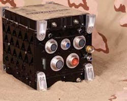
Spray cooling typically is used at the component and box levels, depending on the application type, size, and composition. “If you have a large processor, like a sensor with 15 slots of cards, we apply it at the box level. But if it is an EW [electronic warfare] application, say a jammer with a couple of big power amps that otherwise would have big, heavy heat sinks, we replace those with a couple of coldplates, which don’t have to be in a box. So you would have a pump and heat exchanger; the evaporative process is happening within a closed coldplate that is, essentially, a heat sink on the power amp and not hitting any components,” Baddeley says. “If there are lots of cards in the backplane, it is applied at the box level.
“A third approach, similar to power amp coldplates, applies to C4I in a ground vehicle, where instead of embedded VME you are using 1U boxes in a 19-inch rack,” says Baddeley. “Most components can withstand desert air temperatures–except the processors, which tend to overheat. In those cases, vehicles dedicate air conditioning to cool those processors. We install a coldplate solution to pull heat off the processor and allow the rest of the board to be air-cooled, allowing you to avoid big, heavy, power-hungry air conditioning systems without having to fully encase the rack servers inside a sealed liquid enclosure.”
The bulk of SprayCool’s business involves spraying within sealed enclosures, but the coldplate approach, which has evolved in about the past 18 months, is becoming more common for EW jammers and C4I ground systems. “Our approach is, rather than ruggedize the electronics, we are trying to adapt an enclosure-based solution around the military’s necessity to field commercial-grade hardware. A lot of the technologies we use are driven by the need to make commercial-grade cards survive this harsh environment,” Baddeley says.
Liquid cooling limitations
There are limitations with liquid cooling systems. While most systems are sealed and no fluid actually touches any electronic component, there remains a desire to use a liquid that would not damage a component in case there is a leak.
“When you have an electrically non-conductive fluid, it also tends to be thermally non-conductive, so it is the best from a non-toxic standpoint, but not the best otherwise,” Baddeley acknowledges. “In general, however, a fluid that has good insulative properties also tends to be a poor thermal fluid, so that may be a wish that is never granted. The market has been loud and clear with a complaint that liquid cooling is more expensive than air or conductive cooling; we have identified several ways to get the costs down and will be coming out with solutions we feel will be of real interest to ground vehicles.”
Baddeley expects liquid cooling to experience significant growth in the next few years. “I think we’re just touching the tip of the iceberg, in terms of military electronics. In five years, I would expect to see liquid cooling holding up to 10 percent of the market. Only a percentage of the military electronics market needs liquid cooling today, but higher power and density are growing faster than the average growth rate in electronics. So the demand for advanced cooling is actually growing faster than the overall growth in military electronics.”
To Baddeley and others promoting liquid cooling, the key is the nature of the current concerns–cost, size, and weight reduction, maintenance, and service support.
“Five years ago, the issues were technology risk–can liquid cooling be a reliable, viable solution. No one is asking those questions anymore. Now it’s all about how do you service and support in the field and keep costs down as everyone drives to smaller, lighter weight packages. And to me, that is a sign the market is maturing,” Baddeley says. “In terms of cost, service, and supportability, you hear complaints that liquid cooling is too complex. But it is no longer exotic and complex.”
Whatever the approach to thermal management or the platform requiring it, the end-user community is united on one key point: The ability to have an almost plug-and-play architecture.
Richard Hodges, technology team leader for advanced cooling systems at Parker-Hannifin Gas Turbine Fuel Systems Division in Mentor, Ohio, says he believes one of the best solutions for many future applications is liquid flow through.
“On the horizon, I see single-phase LFT happening, up to about 1000 watts, but then evolving to dual-phase with much higher heat levels within the module; it all depends on the architecture of the electronics, but I can easily see 2000 watts in a single board,” Hodges says.
Another approach involves macrolaminate structures. “The macrolaminate fabrication and design process has to do with designing in layers. We can take very thin layers and put in whatever channeling and topography we want to manage liquid or air gaps for insulation, do manifolding and routing or in several layers to control the fluid to get the best atomization possible,” Hodges explains.
“Macrospray (a patented Parker-Hannifin process) allows us, in a very thin space, to do cooling or provide fluid distribution and make modules for very high heat loads and still maintain original form factors. In that way, we can make very cool coldplates or spray an impingement spray directly on the component and still keep it dry to the rest of the environment. It also allows us to get greater heat densities by use of impingement, by use of two-phase sprays. And we can do surface enhancements with very fine features.”
Although the electronics age may seem old enough to be called mature, it continues to evolve. “The use of fans was a scary new technology decades ago; now we’re seeing the same challenges with liquids; what if the pumps stop or you get a leak? In every case, you have to get past each technology’s inherent obstacles,” says Hodges. “But the end of how high we can go in terms of density and power dissipation is not yet in sight. Indeed, our lifetimes and maybe our kids’ and grandkids’ will pass before we have to worry about seeing the end in sight.”
