Making Sure Military Systems Operate Reliably in Extreme Environments.
Author: Simon Parrett, Conceptual/Structural/Thermal Engineer, Kontron America - S&T Company
To meet demanding military specifications for mobile and interconnected surveillance, communication and operational devices, Kontron uses sophisticated thermal simulation to balance size, weight, power and cooling (SWaP-C) trade-offs for “ruggedized” modular chassis that support customized solutions for mission-critical operations.
Today’s military vehicles depend on the latest state-of-the-art visualization, imaging and networking technologies to improve situational awareness and enable military leaders to make the best possible decisions. Vehicles such as Humvees, armored mine-resistant ambush protected vehicles (MRAPs) and unmanned aerial vehicles (UAVs) increasingly rely on advanced electronics, such as processors and circuitry, in compact systems to support their missions.
To satisfy the military’s demand for these electronic systems that can be adapted to a range of uses, defense contractors must meet a host of requirements and specifications. The devices placed on vehicles, such as battlefield sensor systems, military GPS and next-generation communications equipment must be able to communicate and interact in extreme physical environments where they might be exposed to severe electromagnetic conditions. Military standards require that these devices withstand specified extremes of temperature, vibration, shock, salt spray, sand and chemical exposure. Size, weight, power and cooling (SWaP-C) requirements demand that the electronic systems that power these devices be small enough that they do not hinder mobility.
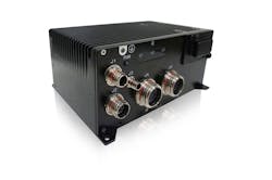
Figure 1: The Kontron Cobalt 901 with RSSD Drive Bay offers a rugged small form factor system in an IP67 Chassis that meets the harshest environmental operational demands. The Intel® Dual Core COM-Express®- based system is tested for extreme temperatures, shock, vibration and EMI conditions.
The approach that has proven most effective is to contain the electronic system functionality in a chassis that has been pre-certified for “ruggedized” operation. Using this chassis, system designers can ensure that the system is maintained in a sealed and temperature-controlled environment. To design these ruggedized systems, Kontron, a global leader in embedded computer technology and an IoT leader, uses sophisticated computational fluid dynamics (CFD) analysis to accurately manage thermal reliability for components and ultimately the complete integrated system. The chassis they provide enables original equipment manufacturers (OEMs) to build customized solutions for mission-critical applications.
Ruggedized Systems
Kontron’s COBALT line of computing platforms uses a modular approach to deliver a rugged, sealed computing system with a specialized carrier board and configurable front panel that can be integrated into the electronics bay of a Humvee, MRAP-type vehicle or UAV. The box-level system provides processing power to enable third-party developers to maintain flexibility, compatibility and interoperability for many types of rugged applications. Using standard interfaces reduces long-term costs and makes it easy to upgrade, replace and reuse capabilities across systems. Many of these systems can be fitted onto a single aircraft or ground vehicle. View the recently published video from a Kontron Technology Event.
To develop a truly flexible system, Kontron must take many variables into account and identify trade-offs. Surveillance applications, for example, require high data rates and fast processing speeds. They also require efficient signal bandwidth for communications, and reliable wireless communication to send information back to data centers. For these applications, customers want a chassis that can ensure that powerful processors or other components do not impair the radio signal. Power consumption and thermal management are also important; the heat from a processor can impede the performance of other components, and thermal cycling stresses as the processor heats and cools, especially in addition to conditions such as extreme desert or the cold of high altitudes, can cause fatigue in components and the chassis. As systems become more complex and are required to incorporate more capabilities, the challenges of managing SWaP-C requirements is even more critical, and design priorities depend upon the size of the vehicle, the nature of the applications and the missions for which applications are employed.
“Defense contractors must meet a host of requirements and specifications to satisfy the military's demand for flexible electronic systems.”
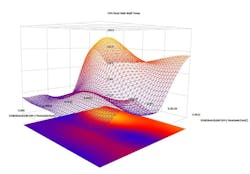
Figure 2: CFD Optimization Response Surfaces
CFD Analysis for Thermal Management, Reliability
To develop these chassis, designers of the COBALT product line have adopted a “five-gate” process of sign-off procedures, from loose specification (Gate 1), through various iterations, to a finished product (Gate 5). Typically, they introduce Computation Fluid Dynamic (CFD) Analysis analysis at Gate 1 to anticipate problems and trade-offs early in the design phase, leading to more complex products in a shorter design frame. The team uses SolidWorks Flow Simulation as our CFD tool that tightly integrates with our 3D CAD models developed in SolidWorks 2018. The SolidWorks Flow Simulation software tools also offer us the benefit of optimizing multiple design parameters simultaneously to derive the optimum solution with the least number of design iterations.
The Kontron design team uses CFD analysis to evaluate and optimize chassis thermal performance. Some key activities are:
- Designing the enclosure to draw as much heat as possible from the circuit board and processor. The team uses SolidWorks Flow Simulation to streamline CFD analysis to design finned surfaces and heat sinks, and arrive at an optimal design.
- Determining placement of electronic components and subsystems within the chassis and balancing the trade-offs necessary to meet SWaP-C requirements. For example, engineers analyze the power dissipated by an expansion board and its effect on the temperature of a nearby processor.
- Reviewing internal thermal conduction paths from high-power components to ensure there are efficient paths to the enclosure walls.
- Exploring external environmental factors in situations where the full system will be deployed. If the system chassis is deployed in a UAV, for example, the cooler temperatures and thinner air in high altitudes will affect thermal management. Another factor might be the location of the chassis in the vehicle. If additional chassis are located nearby, heat and radiation exchange need to be considered.
Besides the early focus on optimal design for SWaP-C considerations, Kontron designers are also concerned about longevity. When the chassis is added to a ground vehicle or plane, it’s expected to last three to five years, plus another two years with maintenance. The mean time before failure (MTBF) is very important to their customers.
Evaluating Design Trade-Offs
Recently, the design team introduced a new gate, Gate Zero, wherein they talk to customers and work with product managers to get new ideas for their products. This enables the team to create “what if” scenarios even before they write the specifications. To test the Gate Zero concept, Kontron engineers modeled a sample heatsink using conceptual designs in our CFD tool and tested various configurations to determine what trade-offs would be required. (A heat sink may appear a relatively trivial part of the system design, but if one includes surface finish / emissivity in addition to geometric variables, there can be eight design parameters to optimize on.)
In the past, they would analyze thermal problems by running an initial analysis, trying some manual design variations, and after seven or eight design iterations that included physical mockups, perform a final analysis and publish their results. Using the Design of Experiments and Optimization functions within our CFD tool, the team was able to exceed those limitations, identifying 240 potential design variations to test. The software then used mathematical models to narrow down the list to just 70 essential variations for further study. By running 70 intelligent design iterations over a weekend, engineers were able to evaluate 10x more design variables than was possible with the old methodology in the same amount of time.
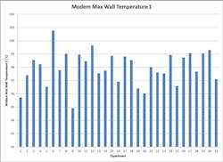
Figure 3: Temperature plot of Modem surface temperature in each Design of Experiments analysis
Having simulated multiple design variations (or experiments), the software tools enables us to build Parameter Response Surfaces where one can explore the interaction and effects of varying one design parameter against another. This provides the engineer enormous insight into the design trade-offs implicit within a design, as you dynamically change one variable and observe the impact on others. At this point one can select the optimum design solution, and perform a final analysis to validate the results.
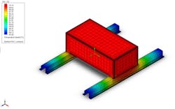
Figure 4: Analysis exploring a variation in mounting configuration. Aluminum block with 50W thermal load in free 55C air, mounted on twin aluminum spars (end of spars held to 55C amb.temp.)
From the large design space that was explored using simulation and leveraging our design optimization tools, the Kontron team developed a chassis configuration tool with an Excel interface that their sales team can use in customer meetings to rapidly design a chassis customized to client requirements.
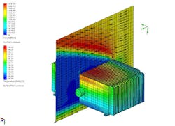
Figure 5: Analysis exploring impact of moving air in addition to natural convection. Kontron Cobalt system with 40W thermal load in 55C air (Radiation considered with e=0.8) plus air moving at 150LFM from rear.
Starting with a baseline configuration with the desired maximum ambient temperature, Application Engineers add design variables, such as CPU max power or electronic expansion trays, operating parameters, such as the orientation and position of the device, and the altitude where it will be used. The spreadsheet shows the power consumption of each component in the enclosure and how their interaction affects the temperature within the box. They can also add remediation options, such as extending the size of the heat sinks, to calculate their effect on the temperature. The spreadsheet can also be used to factor in the cost of changes, for example, the cost of adding a heatsink based on the number of fins and their thickness. Using the inputs and relationships they‘ve learned using optimization software enables them to better inform their customers so they can find the best configuration together..
With the ability to increase virtual testing by a full order of magnitude in less time, Kontron can avoid potential problems, adapt to their customer’s needs and provide rugged, reliable systems for the connected army of the present and future. Kontron uses CFD analysis to accurately manage thermal reliability for components and ultimately the complete integrated system. By running 70 intelligent design iterations over a weekend, engineers were able to evaluate 10x more design variables than was possible with the old methodology in the same amount of time.
With the ability to increase virtual testing by a full order of magnitude in less time, Kontron can anticipate potential problems, adapt to their customer’s needs and provide rugged, reliable systems.

